
Here, we first discuss function modeling activities and techniques. Then, we discuss secure system function (i.e., secure function) modeling. A secure system function model is a function model with security mechanisms integrated into the model. The security mechanisms are in the form of security functions at the function model level.
Function Modeling
The functional aspect of a system is described using a function model. A function model specifies the functional requirements of a system. The term function refers to the tasks and actions a system must perform to support the user’s needs. There are several function modeling methods such as data flow diagramming, use case modeling, and Integrated Definition (IDEF), etc. Here we discuss use case modeling in detail.
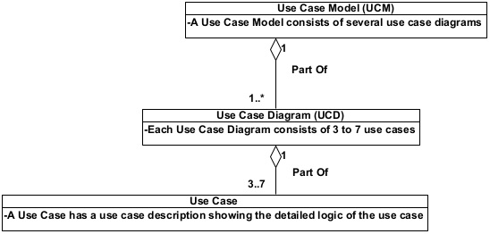
A use case model uses a collection of related use cases to describe the various functions of a system at different levels of details. These use cases are organized in use case diagrams in a hierarchical structure.
Figure 1 shows the relationship between use case model, use case diagrams, and use cases. Any non-trivial system has several levels of use case diagrams. Every use case diagram, except the context level use case diagram, should have at least 3 and not more than 7 plus-minus 2 use cases. The context level use case diagram has a single use case representing the whole system.
A Quick Example of a Use Case Model
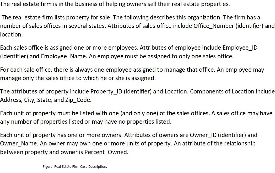
We use a simplified real estate firm case to show an example of a use case model. The case is described in figure 2.
Business Activities of the Real Estate Firm
Here, we identify the business activities of the firm and model the activities in the form of a use case model.
- Maintain property.
- Add a new property.
- Update an existing property.
- Display a list of properties.
- Remove an existing property.
- Maintain owners.
- Add a new owner.
- Update and existing owner.
- Remove an existing owner.
- Search owner properties.
- Display a list of owners.
- Maintain sales office.
- Add a new sales office.
- Change an existing sales office.
- Remove an existing sales office.
- Monitor sales office.
- Maintain Employee.
- Add a new employee.
- Update an existing employee.
- Remove an existing employee.
- List employees.
- Maintain firm.
- Set up firm.
- Update firm.
- List firm.
A well-organized list of business activities of a system are used to develop the use case model of the system.
Use Case Model of the Real Estate Firm
A use case model is a collection of related use case diagrams that capture the functions of a target firm in a hierarchical form. The firm has two types of workers—Manager and Employees. Employees perform the day-to-day activities and managers manage the sales office’s operations. Figure 3 shows the overall context of the real estate firm as a system. Managers and employees are modeled as actors that interact with the firm as a system. The context diagram has a single use case representing the whole system. The context diagram’s purpose is to establish the boundary of a system. The boundary is established by specifying the actors and their interaction with the system. The context diagram is expanded into the next level (level 0) of the use case diagram (UCD) detailing the functions (subfunctions) contained inside the “Real Estate Firm System” use case at the context level.

Figure 3. A Context Use Case Diagram of the Real Estate Firm System.
Figure 4 shows the level 0 use case diagram for the real estate firm system. It has five high level functions (i.e., business use cases). These business use cases are expanded into the lower-level functions (use cases) until all the use cases are at the elementary business process (EBP) level. An EBP is an elemental business process/function that has value to the user, and it must be performed in its entirety at the same time or not at all. An elementary business process is a system use case. So, for example, “Add a new Property” is a system use case (i.e., an EBP) but “Maintain Property” is not an EBP. Maintain Property is a business use case. A business use case must be broken down to the level of system use cases.
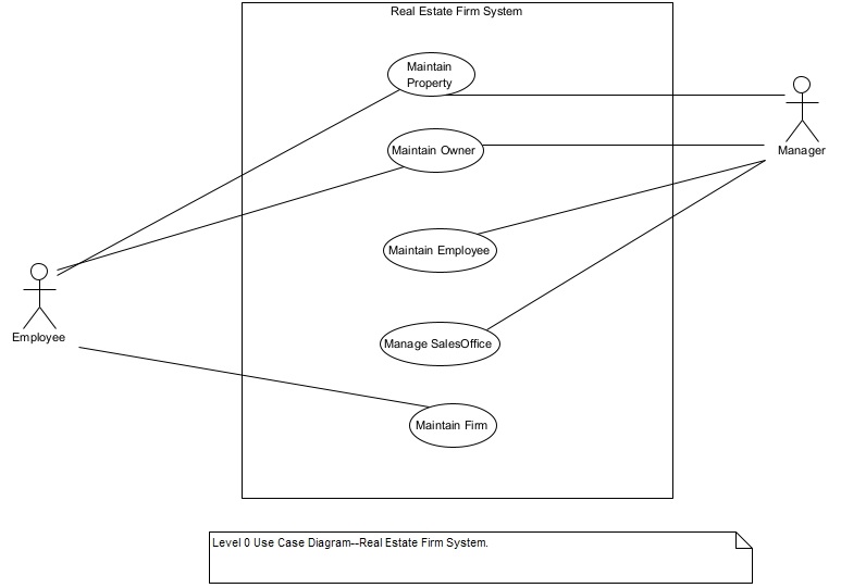
Figure 4. Level 0 Use Case Diagram of the Real Estate Firm System.
Each business use case at level 0 is expanded as a use case diagram at level 1. Figures 5, 6, 7, 8, and 9 show the level 1 use case diagrams. In the real estate firm case, all the level 1 use cases are “system use case”. There is no need to expand them further to the next level.
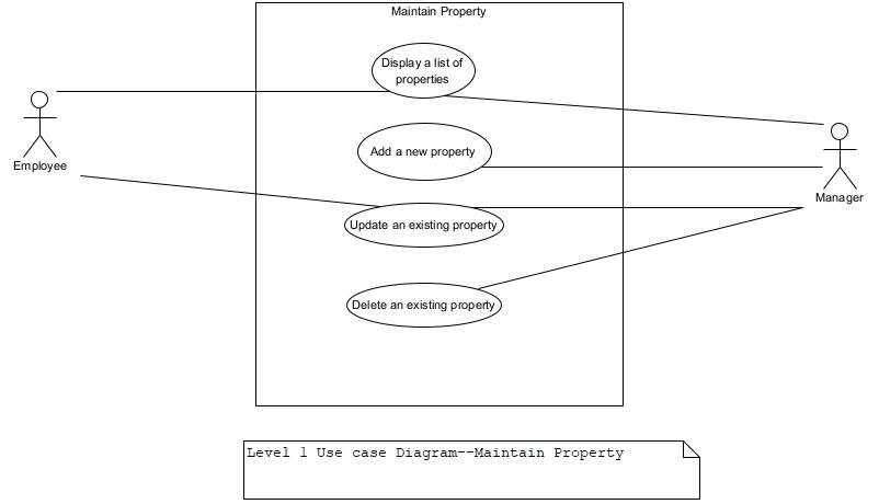
Figure 5. Level 1 UCD–Maintain Property.
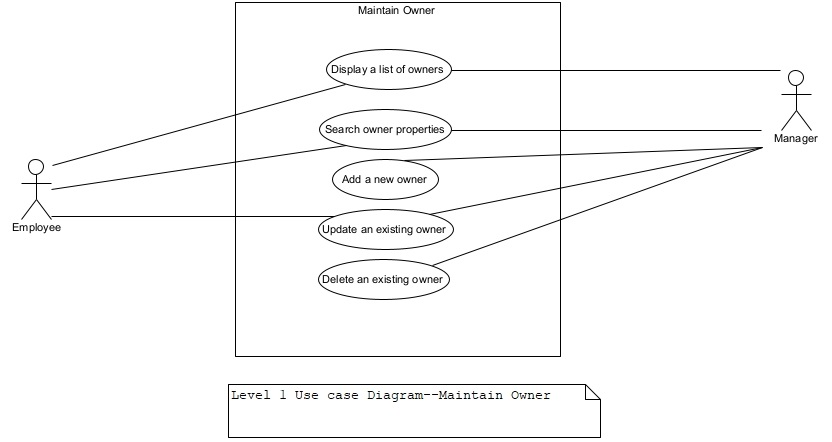
Figure 6. Level 1 UCD–Maintain Owner.
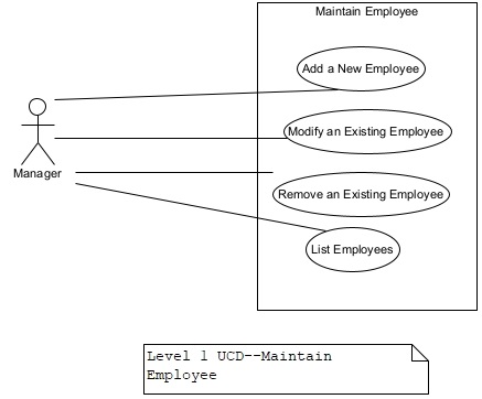
Figure 7. Level 1UCD–Maintain Employee.
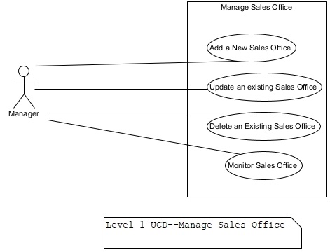
Figure 8. Level 1 UCD–Maintain Sales Office.
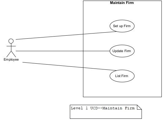
Figure 9. Level 1 use case diagram for Maintain Firm.
Use Case Model–An Introduction
A use case model describes the functionality of a system in a hierarchical structure. We start with the modeling of the business activities of the system and decompose/organize them into sub-activities by introducing details gradually until we identify the sub activities at the elementary level. In other words, we start with the business use cases and gradually decompose them into system use cases. This results in a hierarchy of several levels of use cases with the bottom most level of use cases being the system use cases. Use cases are grouped into use case diagrams. Generally, a business use case is represented by a use case diagram. Each use case is a self-contained unit of function. It does not depend on other use cases. There is no data flow or connection between use cases unlike the dataflow between processes in a Data Flow Diagram. A use case model, as stated above, is a collection of one or more related use case diagrams. A use case diagram includes four major elements:
- The system/subsystem to be described,
- The actors that the system/subsystem interacts with,
- The use cases that the system knows how to perform, and
- The interaction between the actors and the use cases.
As part of the use case modeling, the boundary of a system to be modeled must be defined first. The boundary establishes the context of the system. The boundary of the system is influenced by the purpose and the viewpoint of the modeler. In addition to the purpose and the viewpoint, there are some other factors to consider in establishing the boundary of the system. These are:
- Which tasks are automated, and which are manual? A manual task will be performed by the actor of the system.
- Which tasks are performed by other systems? These tasks will be outside the scope of the system to be modeled. The other systems will be modeled as an actor if they will interact with the system to be modeled.
- The entire solution that the system supplies must be included within the boundary of the system.
It generally takes several levels of use case diagrams to completely define a system unless it is a trivial system.
In UML notation, an oval shaped symbol is used to represent a use case. A rectangle is used to represent the system (i.e., the use case diagram). Figure 10 shows the main symbols used in a use case diagram.
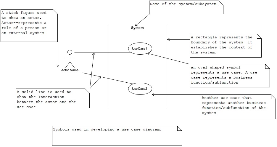 Figure 10. Symbols used in creating a use case diagram. The “System” name on top of the rectangle is also the name of the use case diagram.
An actor represents the role of a person and/or an external system that interacts with the system. It is not an individual user. It is also not a department. A single user may be assigned to play more than one role. It is the role that has “access” to the system and not an individual person. For example, an individual user can be assigned a role of a “clerk” and a role of a “manager.” As a clerk he/she can access (interacts with) a set of use cases, and, as a manager he/she can interact with a different set of use cases. Actors have goals. A goal, here, is a task that the actor wants to get completed with the help of the system. Essentially each use case satisfies an actor’s goal.
A business use case is a higher-level use case that consists of a cluster of either sub-business use cases or system use cases. Business use cases are used to organize system use cases into manageable clusters.
A system use case represents a complete behavior as perceived by an actor. A system use case is an elementary business process. It represents a complete unit of work that is not meaningful to the actor if it is divided further into sequence of steps. A use case is always initiated by an actor.
A use case description describes the internal logic of a system use case. It includes the actor’s actions and system use case’s responses. A use case description can be described textually or using a formal template or an activity diagram. A simple use case can be described textually. However, a medium to complex level use case is described formally using a use case description template that includes pre-conditions, post-conditions, normal and exception logic, etc. We will discuss complex use cases and their descriptions in the next post.
Here, we discuss the secure system function modeling to contrast it with function modeling.
Based upon the description of the firm, the major activities/sub activities are:
Secure Function Modeling
Secure system function modeling or secure function modeling is a modeling activity that integrates security functions consciously into the function model. In a use case model, the concept of misuse case is used to integrate security functions into the function model.
We first describe a simple but effective way to integrate security functions to ward off hackers. Then, we show some secure use case diagrams to illustrate the use of misuse cases to incorporate security use cases in a secure use case diagram.
Security Threats
Security threats arise when a hacker (an insider or an outsider) uses various techniques to gain access into a system. Most of these malicious techniques affecting an application are briefly described below.
Flooding a system
A hacker tries to cripple a system by making many login requests and providing more input than the system can process.
Attacking Application
A hacker uses attack techniques like SQL injection, cross site scripting (XSS), and buffer overflow, etc. to insert malicious code and/or alter the application.
Stealing Data
Stealing of data may involve identity theft, and access to confidential data, etc.
Security Functions
It turns out that we need just four security functions to thwart most of the security attacks on an application. A security function is basically a function responsible for checking and enforcing various security policies and rules. Each system function calls the security functions to deal with a user’s response and before making any modifications to the system. These security functions are listed below.
Validate User Input
This security function uses the motto “trust but verify” every input from a user or any other system. Input security rules and policies can be easily set up and enforced by validating user’s input against the rules and policies. This function can easily thwart the attack of buffer overflow and SQL injection.
Use Strong Authentication
Strong password and two-factor authentication reduce the risk of unauthorized access to a system. This security function enforces strong authentication policies.
Monitor Brute force Attack
This security function can minimize the brute force attack by monitoring and blocking too many logins and other inputs to a system.
Encrypt Communication and Data
Data in-motion and data at-rest should be appropriately encrypted to minimize security risks from eavesdropping and stealing data from a database. At least, confidential data whether in-motion or at-rest must be encrypted appropriately. This security function implements the data encryption policies for communication and for storing in the database.
Secure Use Case Model
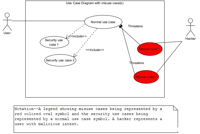
In this section, we show a partial secure use case model for the Real Estate Firm case. We represent security threats from hackers as misuse cases and include secure functions to reduce the security risks for normal use cases. We model a hacker as one of the actors. A misuse case is shown using a red colored oval symbol as shown in figure 11. Figure 11 shows the legend of symbols and notations used in secure use case diagram. A misuse case is a use case with malicious purpose. As shown in figure 11, a misuse case threatens a normal use case(s). Normal use cases include security use cases to deal with the threats from misuse cases. A security use case models a security function.
Secure Use Case Model of the Real Estate Firm
Figure 12 shows a secure context use case diagram for the real estate firm. Here, we have named the system as “Secure Real Estate Firm System.” The context diagram in figure 12 includes a Hacker actor explicitly to emphasize the need to pay attention to security risks.
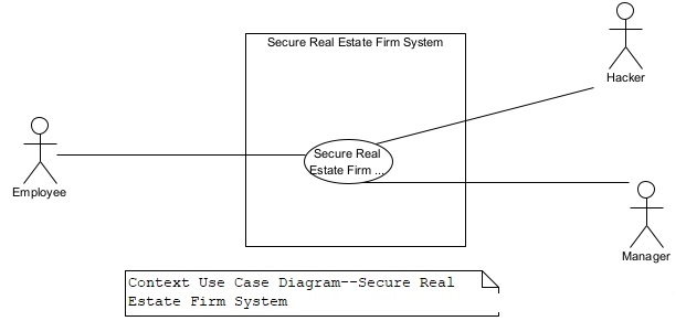
Figure 13 shows the level 0 use case diagram for the secure real estate firm system.
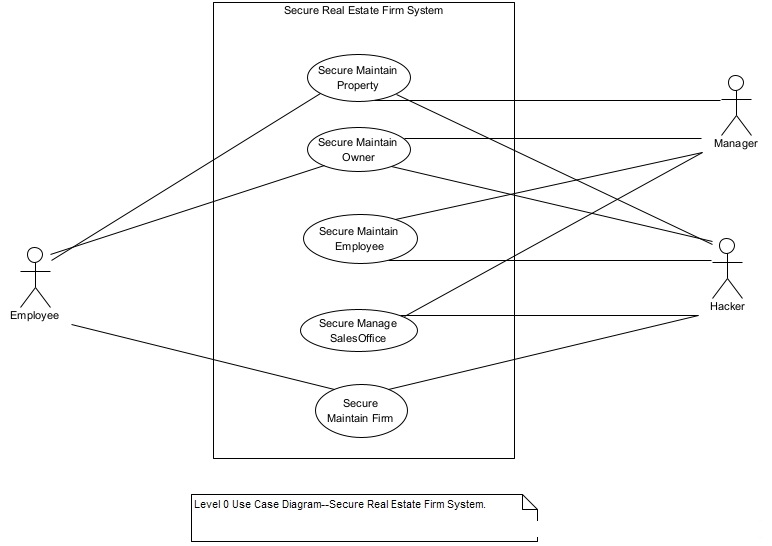
Note that a hacker can try to access any of the five business use cases in figure 13. Each level 0 use case should, as shown, include the word “secure” in its name to further emphasize the security of business use cases.
The business use cases “Secure Maintain Property”, and “Secure Maintain Owner” are expanded at level 1 to show the details inside them. Figures 14 and 15 show the level 1 use case diagrams for Secure Maintain Property and Secure Maintain Owner respectively. Security use cases and misuse cases are included along with the system use cases as shown in figures 14 and 15. In other words, each system use case should be required to use appropriate security use cases to thwart hackers’ attempts using misuse cases.
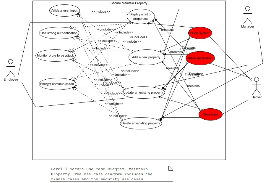
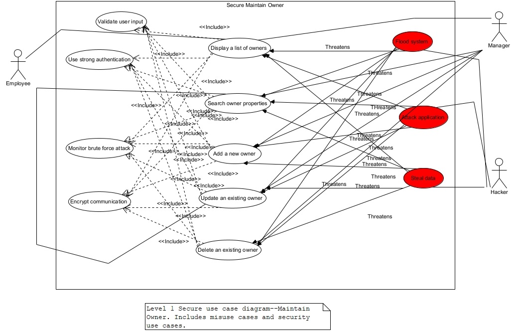
We show level 1 use case diagrams for two business use cases at level 0. The other business uses—Secure Maintain Employee, Secure Manage Sales Office, and Secure Maintain Firm will be expanded at level 1 and the appropriate misuse cases and the security use cases added to the use case diagrams. Our advice is to add at least the above mentioned three misuse cases and four security use cases to every use case diagram containing system use cases.